FEATURES
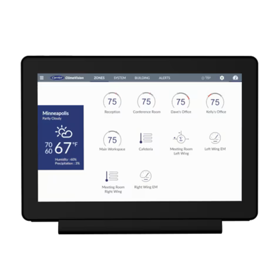
What do you get when you combine a state-of-the-art building sensor and control supervisor and an applied equipment controller for everything from staged DX cooling to analog VFD and coil control? Answer: the ClimaVision Central Control Unit (CCU), a removable wall-mounted tablet and on-site user interface for building management.
Customers appreciate real-time data visualization and graphs, zone and equipment-specific performance and status. The elegant and modern design snaps easily and securely into place with a spring-based locking slider.
The Central Control Unit (CCU) acts as a wall-mounted aggregation gateway for ClimaVision’s wireless terminal equipment modules in a building. The CCU includes a tablet running Android and a Control Mote that provides inputs and outputs for connecting to central plant equipment.
The Central Control Unit (CCU) is a wall-mounted communication gateway. It connects ClimaVision terminal devices via the local 900 MHz wireless mesh network and connects to Modbus devices via RS485. The data it collects from these devices is then sent to the ClimaVision cloud with a Wi-Fi or LAN connection.
The CCU also acts as a zoned AHU controller or optimization extension. It aggregates all the terminal zone data to make more informed decisions about how and when to activate the system AHU.
• Controls air sources for VVT and VAV systems.• Up to 48 terminal equipment modules per Central Control Unit.
• Proactive, predictive control in conjunction with Carrier cloud servers; operates connected to the ClimaVision cloud or standalone without an internet connection.
• Intuitive 8” Android-based user interface
• Acts as a gateway to third-party devices and building automation systems via BACnet or Modbus.
• Powerful MT8163, quad core processor with 2GB RAM and 32 GB Flash Memory
• Easy mobile pairing, configuration and settings setup.
• Status of zones and ability to adjust parameters
• Schedule and setpoint adjustments
• Alerts with severity color coding
COMPATIBLE APPLICATIONS
• VVT
• VAV
• Outside Air Optimization (Economizer) with Smart Node
• VVT Bypass Control Director
SPECIFICATIONS
MECHANICAL• Dimensions: 8.2” x 5.7” x 0.5” (208.5mm x 145mm x 11.5 mm)
• Mounting: (2) #8 screws over standard electrical junction box
• Screen: 8” display, 1200 x 800
• Operating Temp: 32°F to 122°F (0°C to 50°C)
• Termination: Common Pogo Pin termination for USB port and +5V DC power
• Microprocessor: Processor MT8163, quad core, 64-bit, Cortex – A53, 1.3GHz
• HVAC Control: Up to 5 stages of heating/cooling, up to 5 fan stages, 0-10V modulating output for heating/cooling valves (no VFD), and a dehumidifier or humidifier.
WALL PLATE
• Dimensions: 7.96” x 5.1” x 1.02” (202.16mm x 129.29 mm x 25.87mm)
I/O
• Inputs
A. (2) 0-10V analog inputs
B. (2) 10k thermistor inputs
• Outputs
C. (4) 0-10V or 4-20V mA analog outputs
D. (7) 24V DC/1A relays
ELECTRICAL
• Supply: 24V AC/DC
• Consumption: 5 VA (typical), 10 VA (max)
• Battery: 3.7V, 2500mAH, Lithium Polymer
COMMUNICATIONS
• Bluetooth: BLE 4.1 used for pairing devices (e.g. ClimaVision Smart Node equipment control)
• Mesh: 900 MHz IEEE 802.15.4-compliant; used for device communication on mesh network
• Wired: 3-wire sensor bus to wall sensors, 4-wire RS-485 port for Modbus or BACnet
• Wi-Fi: Wi-Fi to connect to internet
INCLUDES
• (1) Central Control Unit• (1) Control Mote Board
| Safety Standards | |
|---|---|
| California Prop 65 | Yes |
| Weights and Dimensions | |
|---|---|
| Operating Weight (lbs) | 2 | Exterior Dimensions (D) (inches) | 9.000000 | Exterior Dimensions (W) (inches) | 6.000000 | Exterior Dimensions (H) (inches) | 2.000000 | Shipping Weight (lbs) | 2.000000 |


